Automated environmental-chamber battery cycler
An automated test setup for cycling battery strings inside a thermally-controlled, insulated chamber, built to study cell performance across temperature under realistic, hard duty cycles.
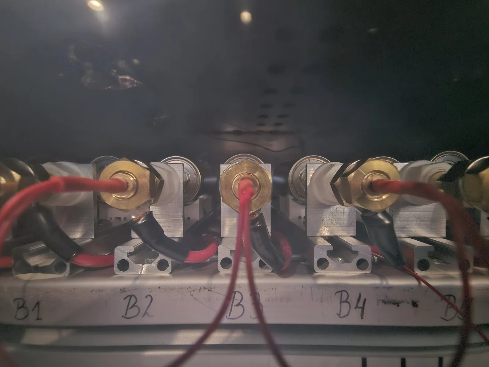
The cell-holder structure carries 6 strings of 7 cells in parallel (42 holders), each holder fitted with high-current, spring-loaded Kelvin (4-wire) pin contacts so the current and voltage-sense paths stay separate. Voltage is measured at the cell, not across the harness. Every holder is individually sensed.
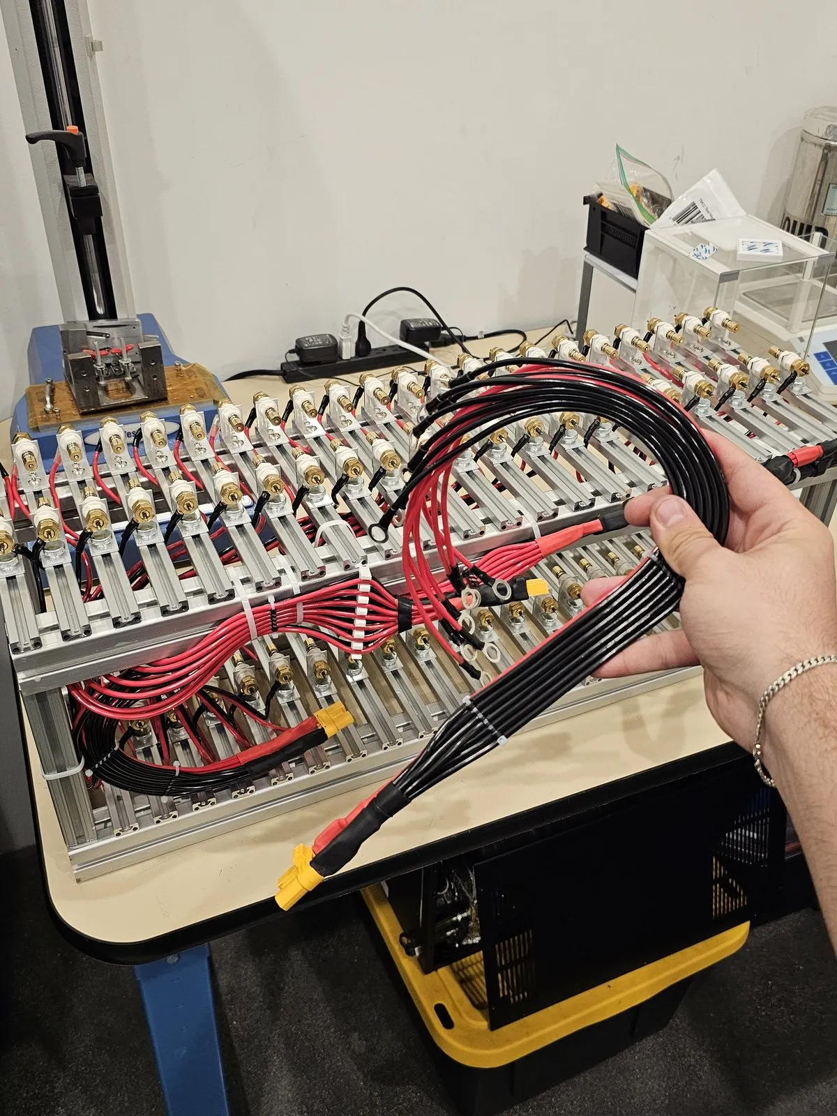
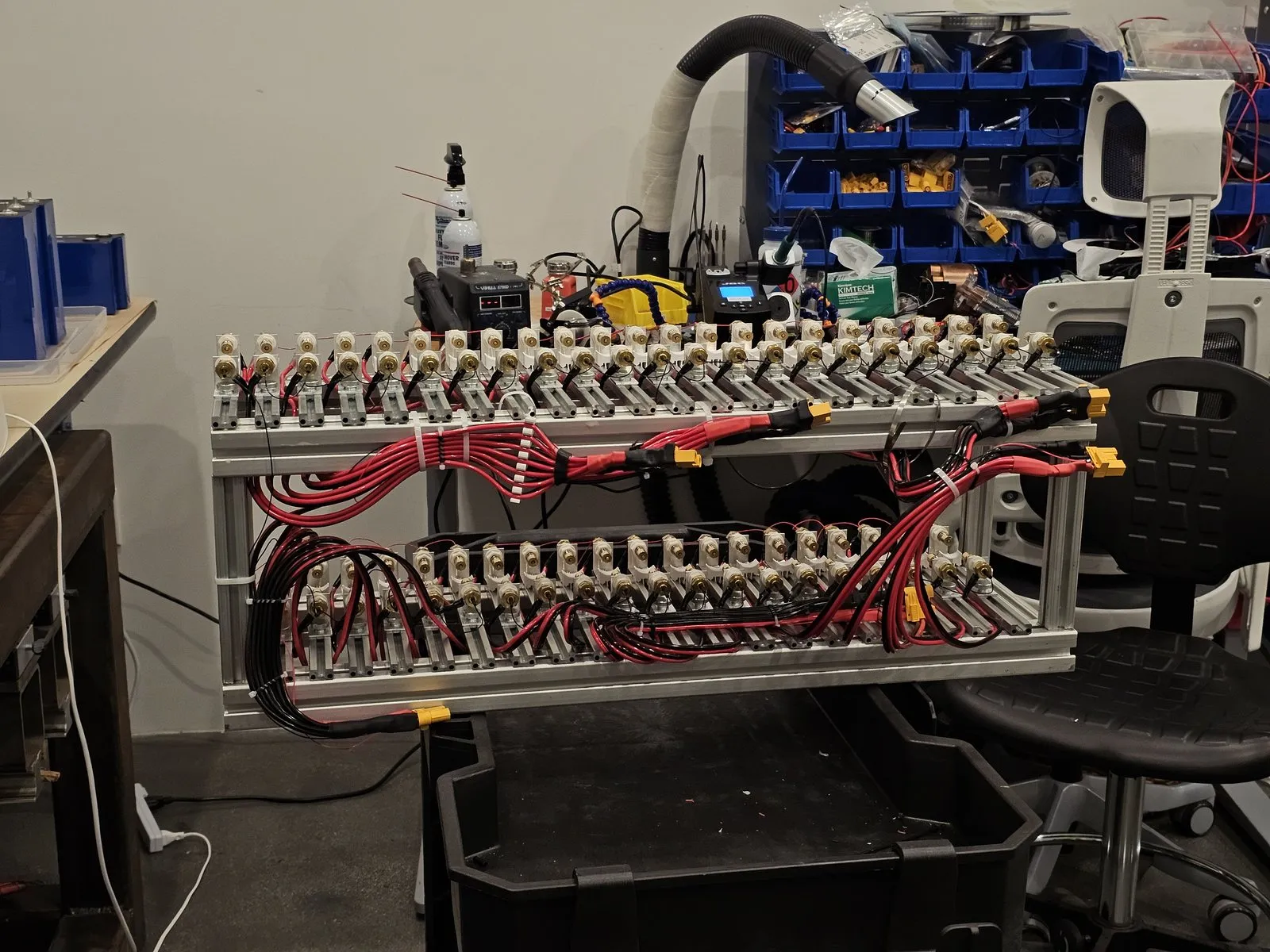
The power harnesses are built as length- and resistance-matched pairs, so charge and voltage distribute evenly across the parallel cells even during very hard cycles. Power distribution runs through Amass XT120 connectors.

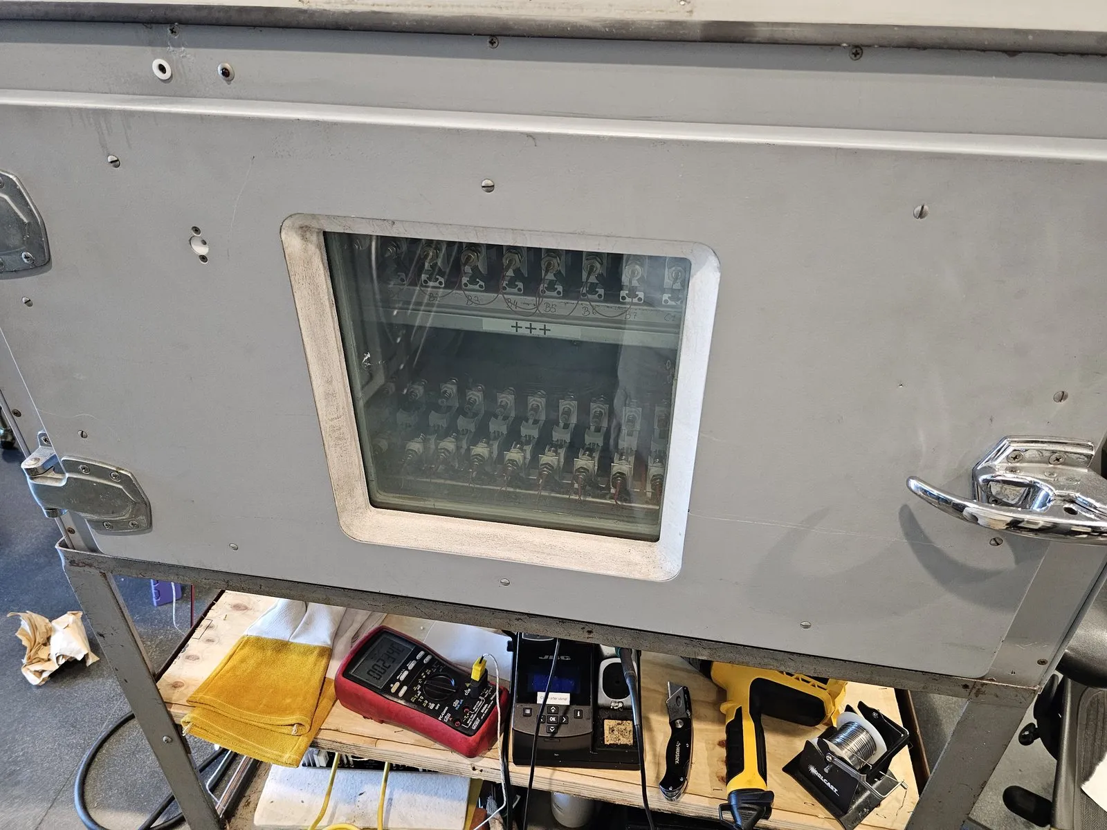
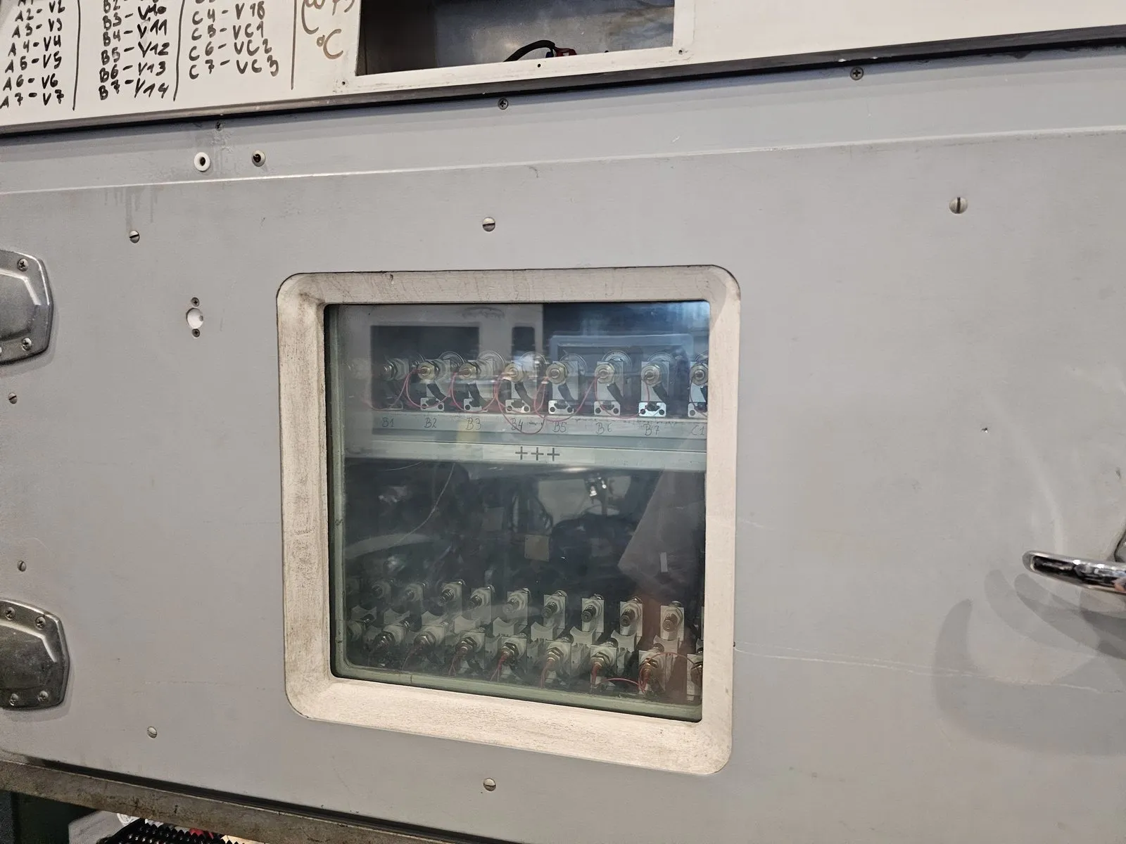
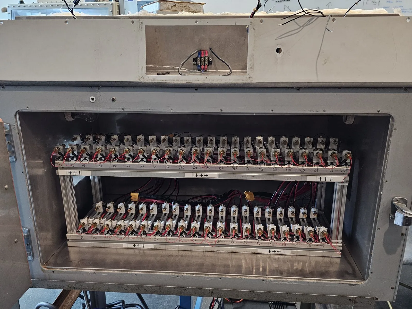
The whole assembly sits inside a thermally insulated chamber before being connected out to the external cyclers.
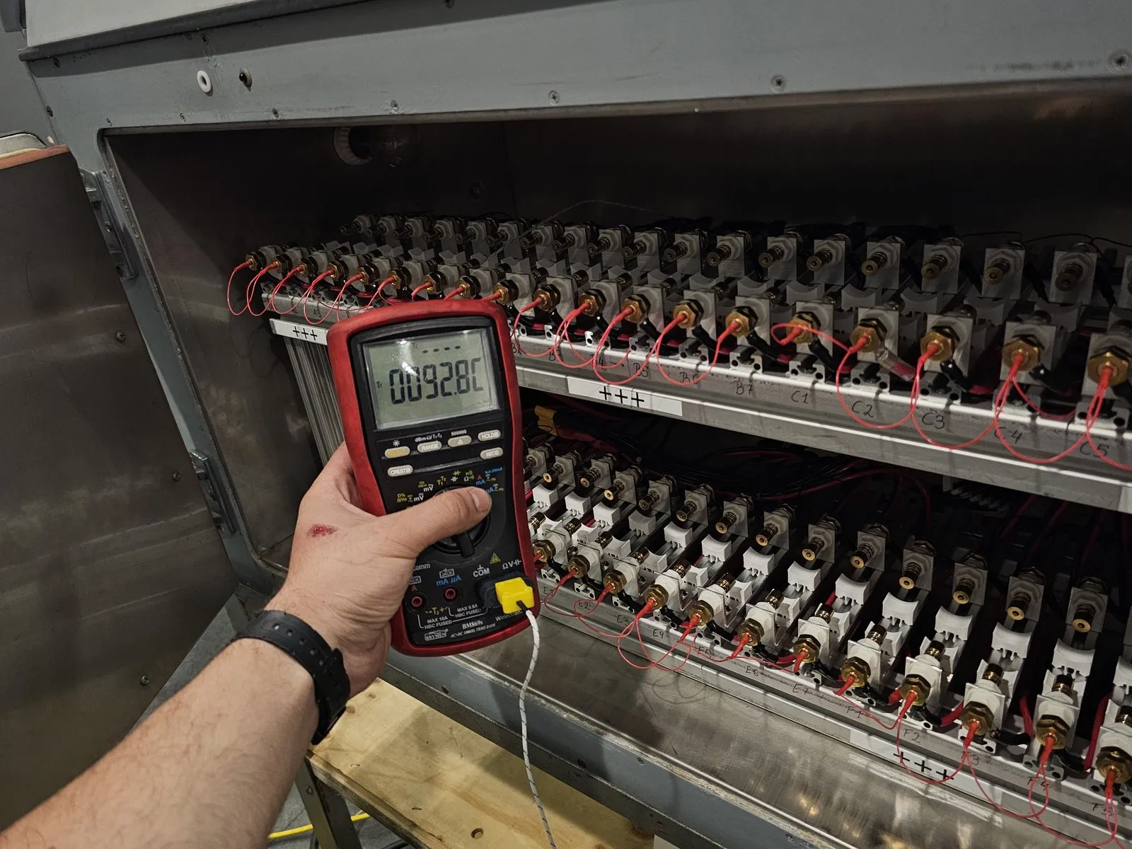
Heating is handled by the internal heater-blowers. An empty test run confirmed the chamber’s heating capability, reaching 92.8 °C:
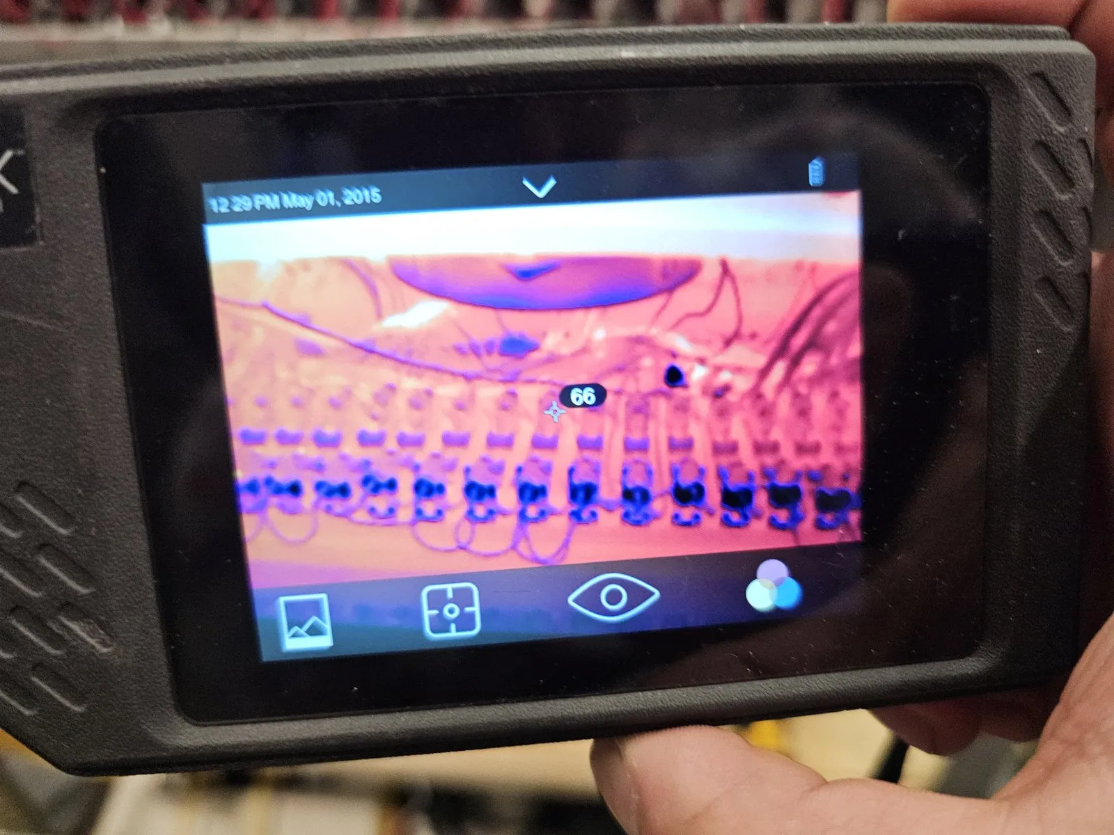
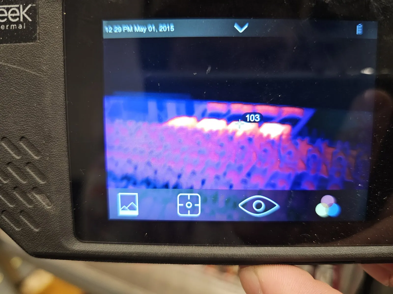
Internal temperatures are cross-checked with a thermal camera:
| Topology | 6 strings × 7 parallel cells (42 holders) |
| Contacts | High-current spring-loaded Kelvin (4-wire) pins |
| Sensing | Per-cell-holder voltage; thermal-camera cross-check |
| Harnessing | Length- & resistance-matched pairs for balanced distribution |
| Power connector | Amass XT120 |
| Thermal | Insulated chamber, internal heater-blowers (verified to 92.8 °C) |
In use, with cells loaded and the chamber closed: